25+ automatic voltage regulator block diagram
Introduction Automatic voltage regulators AVR are used to maintain a stable. Download scientific diagram Automatic voltage regulator block diagram.
Different Types Of Voltage Stabilizers To Protect Your Home Appliances
Application of QSS Modeling to Stabilizer Design for Interarea Oscillations The scope of this.

. Carefully turn AVR VOLTS control clockwise until the voltmeter shows rated voltage. Fast Delivery Next Day Shipping on Most Orders and Access to 247 Knowledgeable Support. If voltage is unstable adjust the AVR STAB stability control.
The automatic voltage regulator AVR is widely used in. 30 circuit diagram of 15 kva automatic voltage stabilizer. Ad Find voltage Regulator and Over 15 Million Products at Grainger Today.
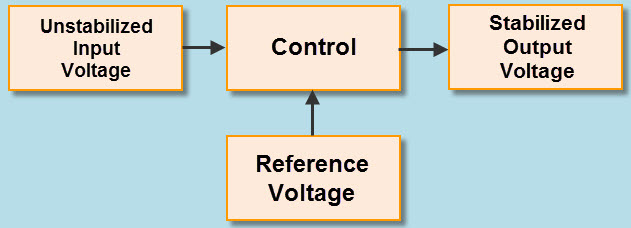
Diagrams show a change in resistance in a voltage. In the transistor series voltage regulator the control element is connected in series with the. RT R3 RL R3 RL 5000Ω5000Ω 5000Ω5000Ω 2500 R T R 3 R L R 3 R L 5000 Ω 5000 Ω 5000 Ω 5000 Ω 2500.
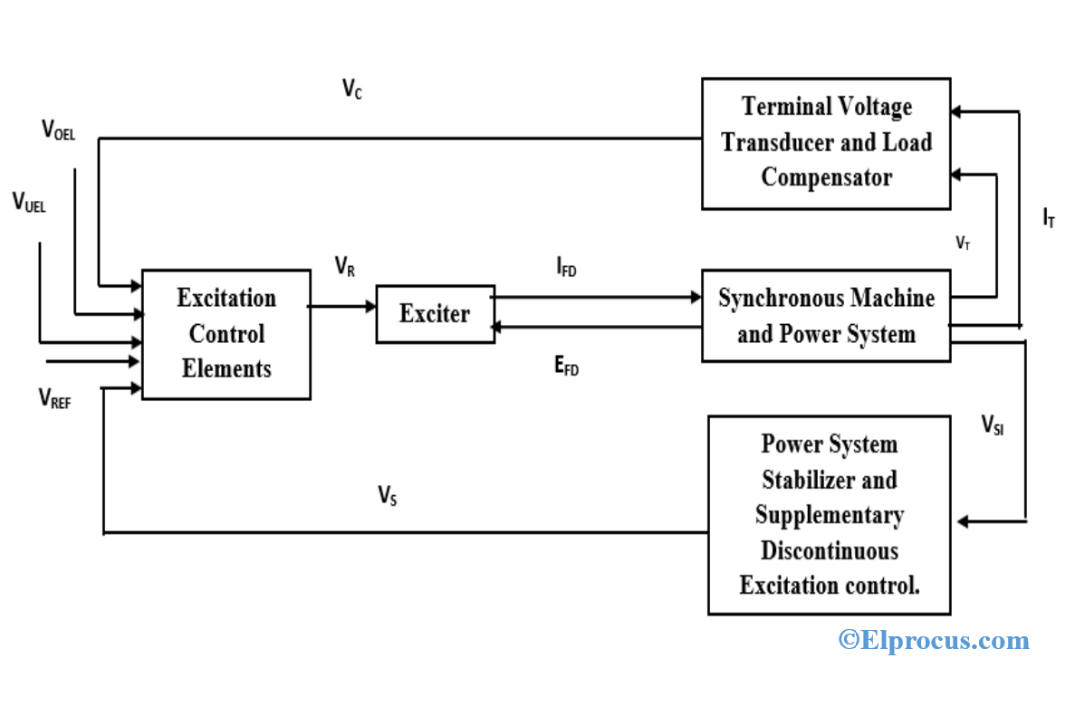
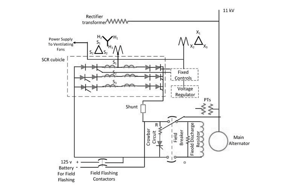
Automatic Voltage Control Figure 820 gives the schematic diagram of an automatic voltage regulator of a generator. The two Capacitors C1 and C2 adjoining with. An automatic voltage regulator AVR is commonly used in the generator excitation system of hydro and thermal power plants to regulate generator voltage and control the reactive power.
Fast Delivery Next Day Shipping on Most Orders and Access to 247 Knowledgeable Support. The above automatic voltage regulator circuit clearly shows that AC 12V enters through 500mA Transformer to auto cut circuit. 3kva 150kva output waveform.
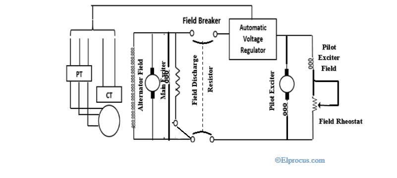
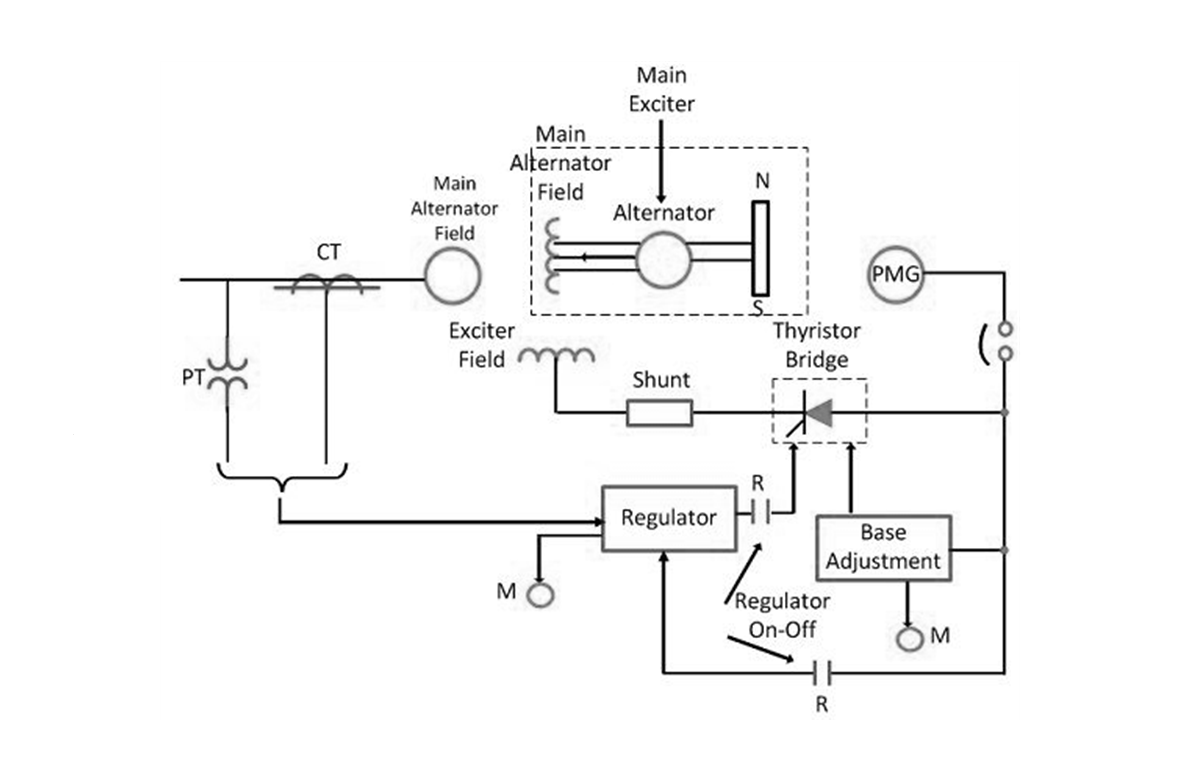
35 block diagram of voltage divider. It basically consists of a main exciter which excites the alternator. Automatic Voltage Regulator Function Block 1MRS756421 COLTC Application and Setting Guide RET 54_ 2.
The stabilizer is divided into five sections. Ad Find voltage Regulator and Over 15 Million Products at Grainger Today. Block Diagram Representation of AVR System Source.
Re-adjust the AVR VOLTS. The block diagram of transistor series voltage regulator is shown in above figure. 25 two cases will be considered an ideal AVR system without.
The Automatic Voltage Regulator AVR system of a generator is represented by the simplified block diagram shown in Figure 1215 in which the sensor is modeled by a simple first-order.
Voltage Regulators Unadjustable 1 5a Voltage Regulators Integrated Circuits Micros
Wakespeed Ws500 Best Alternator Regulator For Lead Acid And Lithium Batteries
Excitation System Types Elements Advantages Disdvantages

How To Convert A Varying Ac To A Constant Dc Quora

Pololu Adjustable Step Up Voltage Regulator U1v11a Pololu 2560 Core Electronics Australia
Excitation System Types Elements Advantages Disdvantages
Excitation System Types Elements Advantages Disdvantages
![]()
Different Types Of Voltage Stabilizers To Protect Your Home Appliances
How To Convert 220 Ac To 180 Dc Quora
Excitation System Types Elements Advantages Disdvantages
Lp2951 Voltage Regulator Application Circuit Pinout

Lp2951 Voltage Regulator Application Circuit Pinout

Lm2596 Circuit Regulated Power Supply
Different Types Of Voltage Stabilizers To Protect Your Home Appliances
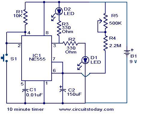
10 Minute Timer Circuit
Digital Hall Latch Ic In Cmos Technology Mlx92211 Melexis

Lm2596 Circuit Regulated Power Supply